CPU Design & Implementation
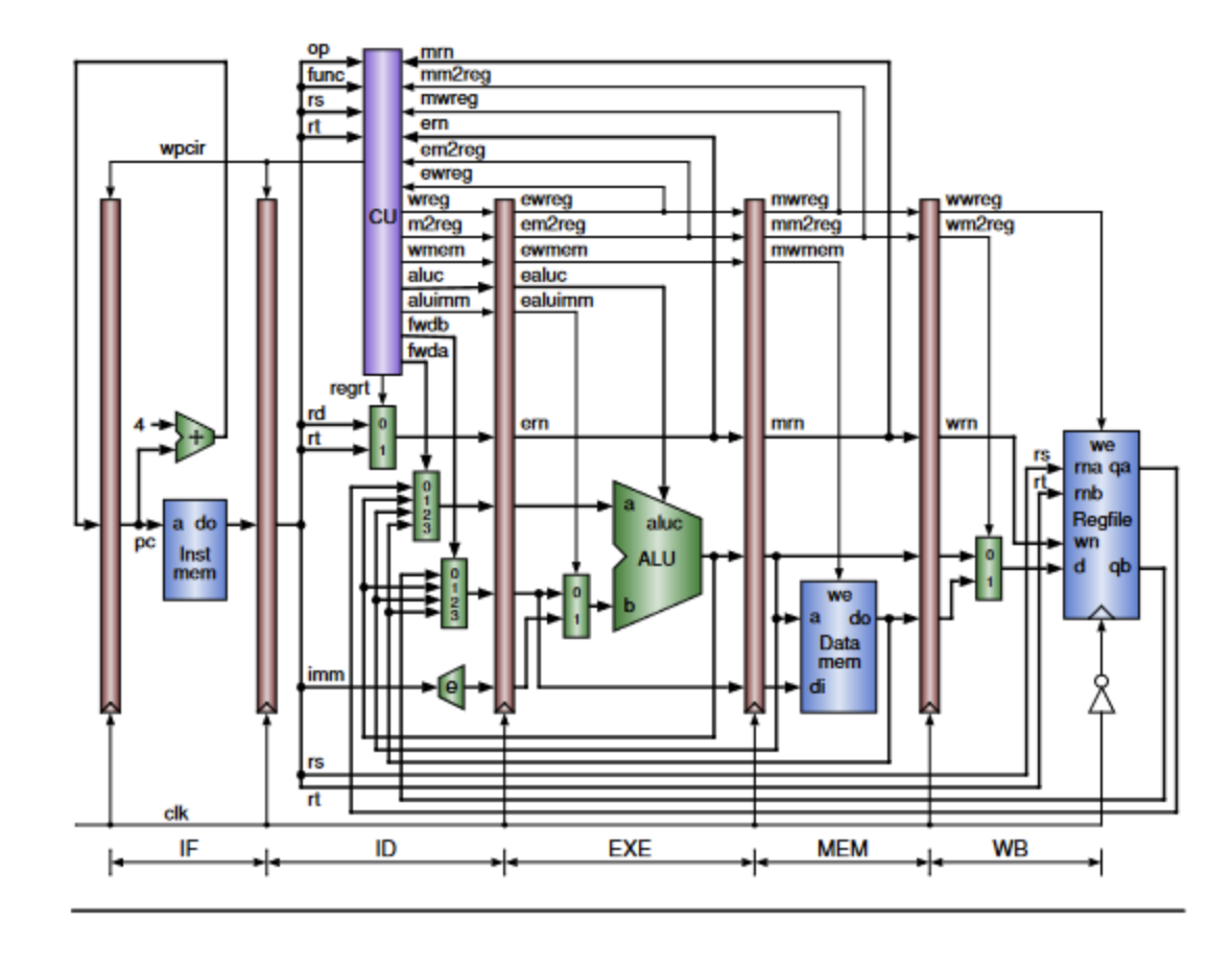
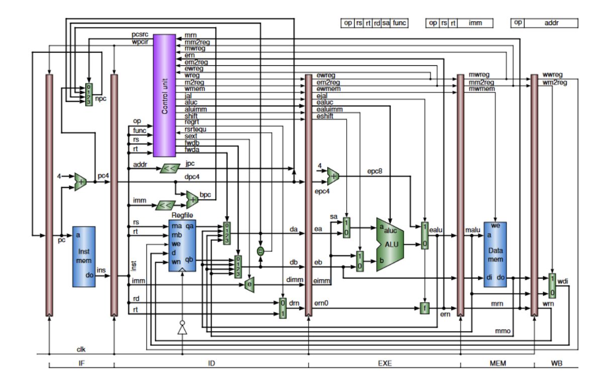
Throughout the course of the semester, we were tasked with building and designing a five-stage pipelined CPU. Verilog, a hardware description language, was used to write and program the CPU. In the first three labs, we mainly focused on implementing the five separate stages of the CPU pipelining process-instruction fetch (IF), instruction decode (ID), execution (EX), memory access (MEM), and writeback (WB). In the final project, we updated the instructions from load word instructions to r-type instructions and made some modifications to the Control Unit so that it could generate the appropriate signals to handle stalls and forwarding to avoid any data hazards and optimize executions as much as possible. (May 2024)
Generally speaking, pipelining allows for increased throughput and decreased response time by executing several instructions in a “staggered” order simultaneously in various stages of the pipeline. This parallel processing technique reduces the response time required to complete a series of instructions, increasing the efficiency of the processor as a result. Moreover, pipelining allows for a higher clock frequency since each of the individual stages can operate simultaneously, or in parallel, that improves the performance of the processor design.
The pipelining process has five stages as briefly mentioned above: instruction fetch (IF), instruction decode (ID), execution (EX), memory access (MEM), and writeback (WB). The IF stage is responsible for fetching the appropriate instruction from memory and calculates the address of the next instruction, either by adding four to the program counter to get the next instruction in series, moving to a new address based on whether a condition is true (i.e., conditional), or jumping to an entirely new address (i.e., unconditional). The ID stage decodes the instruction to determine which operation is being performed (i.e., addition, and, subtraction, or, xor, etc.) and reads the values of the operands. The EX stage performs the specified operation depending on the ALU control line; this is the stage where arithmetic and logic operations are executed with the help of the ALU. The MEM stage, if necessary, accesses the memory to either read or write data to a particular address, depending on if it is a load or store word instruction, respectively. Typical r-type instructions, of course, do not have any need to access the memory. Lastly, the WB stage is responsible for writing back the result of the computation to the register file located in the ID stage, updating the register file with the new calculated value.
Recently, we added another feature called data forwarding to the pipeline to optimize performance and avoid potential data hazards. Data hazards occur when an incorrect result is computed because of using the non-updated value from a previous instruction. With the aid of forwarding, it will allow us to forward the result of an instruction in the EX stage to either the input of the EX stage or the input of the MEM stage for another separate instruction, depending on when the value is needed of course. This is a powerful idea because it allows us to skip the need of waiting for the data to be written back to the register file in the WB stage. As such, forwarding reduces stalls and improves the throughput since execution can proceed as quickly as possible without any unnecessary delays in between. Indeed, implementing forwarding will drastically improve the processor’s overall efficiency and speed.

